路由器故障:OSPF配置错误导致网络无法ping通
OSPF配置错误导致网络无法ping通的故障的解决步骤如下:
网络环境
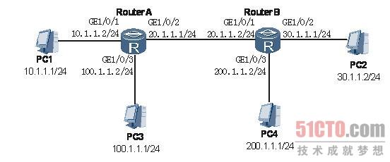
如下图的网络配置中,PC1-RouterA-RouterB-PC2之间通过2M线路相连,运行OSPF协议,并引入直连、静态路由。PC3-RouterA-RouterB-PC4之间模拟新增加的一条100M链路,运行OSPF协议,也引入直连和静态路由。RouterA和RouterB都在area0。
OSPF组网图
配置完成之后发现PC1与PC2之间能够Ping通,但是PC3与PC4之间却无法Ping通。
#p#
故障分析
步骤 1 在路由器RouterA上执行ping 30.1.1.1命令,能够Ping通,说明路由器A和B之间的物理链路没有问题。
具体RouterA为例:
- [RouterA] ping 30.1.1.1
- PING 30.1.1.1: 56 data bytes, press CTRL_C to break
- Reply from 30.1.1.1: bytes=56 Sequence=1 ttl=255 time=60 ms
- Reply from 30.1.1.1: bytes=56 Sequence=2 ttl=255 time=80 ms
- Reply from 30.1.1.1: bytes=56 Sequence=3 ttl=255 time=40 ms
- Reply from 30.1.1.1: bytes=56 Sequence=4 ttl=255 time=80 ms
- Reply from 30.1.1.1: bytes=56 Sequence=5 ttl=255 time=20 ms
- --- 30.1.1.1 ping statistics ---
- 5 packet(s) transmitted
- 5 packet(s) received
- 0.00% packet loss
- round-trip min/avg/max = 20/56/80 ms
步骤 2 在RouterA、RouterB上执行display ospf routing,发现没有RouterB上没有PC3所在网段的路由信息。
以RouterB的具体显示为例。
- [RouterB] display ospf routing
- OSPF Process 1 with Router ID 100.1.1.2
- Routing Tables
- Routing for Network
- Destination Cost Type NextHop AdvRouter Area
- 30.1.1.0/24 3124 Stub 20.1.1.2 200.1.1.2 0.0.0.0
- 200.1.1.0/24 3124 Stub 20.1.1.2 200.1.1.2 0.0.0.0
- 20.1.1.0/24 1562 Stub 20.1.1.1 100.1.1.2 0.0.0.0
- 10.1.1.0/24 1562 Stub 10.1.1.2 100.1.1.2 0.0.0.0
- Routing for ASEs
- Destination Cost Type Tag NextHop AdvRouter
- 20.1.1.1/32 1 Type2 1 20.1.1.2 200.1.1.2
- 30.1.1.2/32 1 Type2 1 20.1.1.2 200.1.1.2
- 200.1.1.1/32 1 Type2 1 20.1.1.2 200.1.1.2
- Total Nets: 7
- Intra Area: 4 Inter Area: 0 ASE: 3 NSSA: 0
步骤 3 在RouterA和RouterB上执行display ospf peer命令,发现RouterA和PC3没有建立OSPF邻居。
RouterA具体显示。
- [RouterA] display ospf peer
- OSPF Process 1 with Router ID 100.1.1.2
- Neighbors
- Area 0.0.0.0 interface 10.1.1.2(Gigabitethernet 1/0/0)'s neighbors
- Router ID: 10.1.1.1 Address: 10.1.1.1
- State: Full Mode:Nbr is Slave Priority: 1
- DR: None BDR: None MTU: 0
- Dead timer due in 41 sec
- Neighbor is up for 00:46:52
- Authentication Sequence: [ 0 ]
- Neighbors
- Area 0.0.0.0 interface 20.1.1.1(Gigabitethernet1/0/1)'s neighbors
- Router ID: 200.1.1.2 Address: 20.1.1.2
- State: Full Mode:Nbr is Master Priority: 1
- DR: None BDR: None MTU: 0
- Dead timer due in 36 sec
- Neighbor is up for 00:42:29
- Authentication Sequence: [ 0 ]
步骤 4 在RouterA和RouterB上分别执行display current-configuration configuration ospf命令,对比发现在RouterA上没有用network命令将PC4所在100.1.1.0/24网段发布出去。
RouterA具体显示。
- [RouterA] display current-configuration configuration ospf
- #
- ospf 1
- import-route direct
- import-route static
- area 0.0.0.0
- network 10.1.1.0 0.0.0.255
- network 20.1.1.0 0.0.0.255
- #
RouterB具体显示。
- [RouterB] display current-configuration configuration ospf
- #
- ospf 1
- import-route direct
- import-route static
- area 0.0.0.0
- network 20.1.1.0 0.0.0.255
- network 30.1.1.0 0.0.0.255
- network 200.1.1.0 0.0.0.255
- #
- return
步骤 5 在RouterA上配置network 100.1.1.0 0.0.0.255,然后执行display ospf peer命令,和PC3的OSPF邻居建立,在PC3上Ping PC4的IP地址200.1.1.1,能够Ping通。
具体PC3的显示。
- [RouterA] display ospf peer
- OSPF Process 1 with Router ID 100.1.1.1
- Neighbors
- Area 0.0.0.0 interface 100.1.1.1(Gigabitethernet6/0/0)'s neighbors
- Router ID: 100.1.1.2 Address: 100.1.1.2
- State: Full Mode:Nbr is Master Priority: 1
- DR: None BDR: None MTU: 0
- Dead timer due in 34 sec
- Neighbor is up for 00:09:36
- Authentication Sequence: [ 0 ]
- [PC3] ping 200.1.1.1
- PING 200.1.1.1: 56 data bytes, press CTRL_C to break
- Reply from 200.1.1.1: bytes=56 Sequence=1 ttl=253 time=70 ms
- Reply from 200.1.1.1: bytes=56 Sequence=2 ttl=253 time=40 ms
- Reply from 200.1.1.1: bytes=56 Sequence=3 ttl=253 time=100 ms
- Reply from 200.1.1.1: bytes=56 Sequence=4 ttl=253 time=70 ms
- Reply from 200.1.1.1: bytes=56 Sequence=5 ttl=253 time=100 ms
- --- 200.1.1.1 ping statistics ---
- 5 packet(s) transmitted
- 5 packet(s) received
- 0.00% packet loss
- round-trip min/avg/max = 40/76/100 ms
故障解决。
在构建OSPF网络时,只有对链路的正确宣告,路由器才会建立邻居关系,根据LSA计算得出转发路径。
----结束
#p#
处理步骤
在RouterA执行以下操作:
步骤 1 执行命令system-view,进入系统视图。
步骤 2 执行命令ospf [ process-id ],进入OSPF进程视图。
步骤 3 执行命令area area-id,进入OSPF区域视图。
步骤 4 执行命令network ip-address wildcard-mask,配置区域所包含的网段。
步骤 5 执行命令return退回到用户视图,执行命令save,保存对配置的修改。
具体以RouterA的显示为例。
- [RouterA] ospf 1
- [RouterA-ospf-1] area 0
- [RouterA-ospf-1-area-0.0.0.0] network 100.1.1.0 0.0.0.255
- [RouterA-ospf-1-area-0.0.0.0] quit
- [RouterA-ospf-1] quit
- [RouterA] display ospf peer
- OSPF Process 1 with Router ID 100.1.1.2
- Neighbors
- Area 0.0.0.0 interface 10.1.1.2(Gigabitethernet1/0/0)'s neighbors
- Router ID: 10.1.1.1 Address: 10.1.1.1
- State: Full Mode:Nbr is Slave Priority: 1
- DR: None BDR: None MTU: 0
- Dead timer due in 38 sec
- Neighbor is up for 01:05:56
- Authentication Sequence: [ 0 ]
- Neighbors
- Area 0.0.0.0 interface 20.1.1.1(Gigabitethernet1/0/1)'s neighbors
- Router ID: 200.1.1.2 Address: 20.1.1.2
- State: Full Mode:Nbr is Master Priority: 1
- DR: None BDR: None MTU: 0
- Dead timer due in 41 sec
- Neighbor is up for 01:01:33
- Authentication Sequence: [ 0 ]
- Neighbors
- Area 0.0.0.0 interface 100.1.1.2(Gigabitethernet1/0/2)'s neighbors
- Router ID: 100.1.1.1 Address: 100.1.1.1
- State: Full Mode:Nbr is Slave Priority: 1
- DR: None BDR: None MTU: 0
- Dead timer due in 31 sec
- Neighbor is up for 00:00:06
- Authentication Sequence: [ 0 ]
----结束
完成上述操作后,PC3能够PING通PC4,故障排除。
案例总结
在构建OSPF网络时,只有对链路的正确宣告,路由器才会建立邻居关系,根据LSA计算得出转发路径。
直连路由的引入只能发生在网络的末端,即叶节点,它不作为SPF计算的一部分,因此不能误认为直连路由的引入就等同于对链路的宣告。
【编辑推荐】
- 路由器故障:策略路由配置不生效
- 路由器故障:POS接口修改MTU值无法生效
- 路由器故障:POS接口无法收到对端的报文
- 路由器故障:ACL反掩码配置错误 策略路由失效
- 路由器故障:MP Group成员接口状态频繁Up/Down
下一篇:Oracle中几个限制的说明